

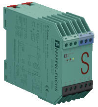
Switch Amplifier KHA6-SH-Ex1
- 1-channel isolated barrier
- 115/230 V AC supply
- Input for approved dry contacts or SN/S1N sensors
- Relay contact output
- Fault indication output
- Line fault detection (LFD)
- Up to SIL 3 acc. to IEC/EN 61508
- Up to PL d acc. to EN/ISO 13849


Please note: All product-related documents, such as certificates, declarations of conformity, etc., which were issued prior to the conversion under the name Pepperl+Fuchs GmbH or Pepperl+Fuchs AG, also apply to Pepperl+Fuchs SE.
Dane techniczne KHA6-SH-Ex1
| General specifications | ||
|---|---|---|
| Signal type | Digital Input | |
| Functional safety related parameters | ||
| Safety Integrity Level (SIL) | SIL 3 | |
| Performance level (PL) | PL d | |
| Supply | ||
| Connection | terminals 22, 23, 24 | |
| Rated voltage | 85 ... 253 V AC , 45 ... 65 Hz | |
| Rated current | 30 mA ± 5 mA | |
| Power dissipation | 2.2 W | |
| Power consumption | max. 2.3 W | |
| Input | ||
| Connection side | field side | |
| Connection | terminals 10+, 12- | |
| Open circuit voltage/short-circuit current | approx. 8.4 V DC / approx. 11.7 mA | |
| Lead resistance | ≤ 50 Ω, in hazardous area cable capacitances and inductivities are to be taken into account | |
| Switching point | ||
| Relay de-energized | I < 2.1 mA and I > 5.9 mA | |
| Relay energized | 2.8 mA < I < 5.3 mA | |
| Response delay | ≤ 1 ms | |
| Output | ||
| Connection side | control side | |
| Connection | output I: terminals 13, 14 ; output II: terminals 15, 21 ; output III: terminals 16+, 17- | |
| Output I | relay , signal | |
| Contact loading | 253 V AC/1 A/cos φ ≥ 0.7; 24 V DC/1 A resistive load | |
| Mechanical life | 50 x 106 switching cycles | |
| Output II | relay , signal | |
| Contact loading | 253 V AC/1 A/cos φ ≥ 0.7; 24 V DC/1 A resistive load | |
| Mechanical life | 50 x 106 switching cycles | |
| Output III | electronic output, passive , fault signal | |
| Rated voltage | 10 ... 30 V DC | |
| Signal level | 1-signal: (L+) -2.5 V (7 mA, short-circuit proof) / 0-signal: blocked output (Leakage current ≤ 10 µA) |
|
| Transfer characteristics | ||
| Switching frequency | 5 Hz | |
| Indicators/settings | ||
| Display elements | LEDs | |
| Labeling | space for labeling at the front | |
| Directive conformity | ||
| Electromagnetic compatibility | ||
| Directive 2014/30/EU | EN 61326-1:2013 (industrial locations) | |
| Low voltage | ||
| Directive 2014/35/EU | EN 61010-1:2010+A1:2019+A1:2019/AC:2019 | |
| Machinery Directive | ||
| Directive 2006/42/EC | EN/ISO 13849-1:2015 | |
| Conformity | ||
| Electromagnetic compatibility | NE 21:2017 , EN 61326-3-1:2017 | |
| Degree of protection | IEC 60529:2001 | |
| Safety | IEC/EN 61508:2010 | |
| Ambient conditions | ||
| Ambient temperature | -20 ... 60 °C (-4 ... 140 °F) | |
| Mechanical specifications | ||
| Degree of protection | IP20 | |
| Connection | screw terminals | |
| Mass | approx. 280 g | |
| Dimensions | 40 x 93 x 115 mm (1.6 x 3.7 x 4.5 inch) (W x H x D) , housing type E | |
| Height | 107 mm | |
| Width | 40 mm | |
| Depth | 115 mm | |
| Mounting | on 35 mm DIN mounting rail acc. to EN 60715:2001 | |
| Data for application in connection with hazardous areas | ||
| EU-type examination certificate | PTB 00 ATEX 2043 | |
| Marking |  II (1)G [Ex ia Ga] IIC II (1)D [Ex ia Da] IIIC I (M1) [Ex ia Ma] I II (1)G [Ex ia Ga] IIC II (1)D [Ex ia Da] IIIC I (M1) [Ex ia Ma] I |
|
| Input | Ex ia | |
| Voltage | 9.56 V | |
| Current | 16.8 mA | |
| Power | 41 mW (linear characteristic) | |
| Supply | ||
| Maximum safe voltage | 253 V AC/DC (Attention! The rated voltage can be lower.) | |
| Output | ||
| Contact loading | 253 V AC/1 A/cos φ ≥ 0.7; 24 V DC/1 A resistive load | |
| Maximum safe voltage | output I/output II: 253 V AC/DC (Attention! Um is no rated voltage.) | |
| Galvanic isolation | ||
| Input/Output | safe electrical isolation acc. to IEC/EN 60079-11, voltage peak value 375 V | |
| Input/power supply | safe electrical isolation acc. to IEC/EN 60079-11, voltage peak value 375 V | |
| Directive conformity | ||
| Directive 2014/34/EU | EN IEC 60079-0:2018+AC:2020 , EN 60079-11:2012 | |
| General information | ||
| Supplementary information | Observe the certificates, declarations of conformity, instruction manuals, and manuals where applicable. For information see www.pepperl-fuchs.com. | |
Classifications
| System | Classcode |
|---|---|
| ECLASS 13.0 | 27210121 |
| ECLASS 12.0 | 27210121 |
| ECLASS 11.0 | 27210121 |
| ECLASS 10.0.1 | 27210121 |
| ECLASS 9.0 | 27210121 |
| ECLASS 8.0 | 27210121 |
| ECLASS 5.1 | 27210121 |
| ETIM 9.0 | EC001485 |
| ETIM 8.0 | EC001485 |
| ETIM 7.0 | EC001485 |
| ETIM 6.0 | EC001485 |
| ETIM 5.0 | EC001485 |
| UNSPSC 12.1 | 32101514 |
Details: KHA6-SH-Ex1
This isolated barrier is used for intrinsic safety applications.
The device transfers digital signals (SN/S1N proximity sensors or approved dry contacts) from a hazardous area to a safe area.
The input controls 1 relay contact output with 3 NO contacts (1 output is in series to the both output relays for the safety function), 1 relay contact output with 1 NO contact, and 1 passive transistor output (fault indication output).
Unlike an SN/S1N series proximity sensor, a mechanical contact requires a 10 kΩ resistor to be placed across the contact in addition to a 1.5 kΩ resistor in series.
Lead breakage (LB) and short circuit (SC) conditions of the control circuit are continuously monitored.
During an fault condition, the fault indication output energizes and outputs I and II de-energize.
For safety applications up to SIL 3, output I must be used. For safety applications up to SIL 2, output I and output II can be used.
Datasheet: KHA6-SH-Ex1
| Datasheet | Typ pliku | Rozmiar pliku |
|---|---|---|
| Datasheet KHA6-SH-Ex1 | 1192 KB | |
| Fiche de données KHA6-SH-Ex1 | 1313 KB | |
| Datenblatt KHA6-SH-Ex1 | 1195 KB | |
| Datasheet KHA6-SH-Ex1 | 1358 KB | |
| Hoja de datos KHA6-SH-Ex1 | 1313 KB |
Documents: KHA6-SH-Ex1
CAD+CAE: KHA6-SH-Ex1
| EPLAN | Typ pliku | Rozmiar pliku |
|---|---|---|
| CAE EPLAN Data Portal / CAE EPLAN Data Portal | LINK | --- |
| CAE EPLAN macro EDZ / CAE EPLAN Makro EDZ | EDZ | 80 KB |
Approvals+Certificates: KHA6-SH-Ex1
Produkty powiązane: KHA6-SH-Ex1
| Matching System Components | ||||||
|---|---|---|---|---|---|---|
|
||||||
| Accessories | ||||||
|
||||||
|
||||||
|
||||||


Choose from various selection criteria like safety integrity level, performance level, device function, and signal type and find the SIL/PL assessed device that you are looking for.


Pepperl+Fuchs Sp. z o.o.
ul. Owsiana 12
03-825 Warszawa
Polska
NIP: 522-28-27-777
 +48 22 256 9770
Pepperl+Fuchs jest czołową firmą konstruującą i produkującą czujniki elektroniczne oraz inne komponenty dla globalnego rynku automatyki. Innowacyjność, wysoka jakość oraz stały rozwój firmy powodują, iż z sukcesem jesteśmy obecni na rynku od ponad 70 lat. Pepperl+Fuchs zatrudnia ponad 6300 pracowników na całym świecie i ma swoje zakłady produkcyjne w Niemczech, USA, Singapurze, na Węgrzech, w Indonezji i Wietnamie. Większość z nich posiada certyfikat ISO 9001.